Raspberry Pi Pico Temperature Sensor
Using the raspberry pi pico microcontroller board with a DHT11 sensor, it tracks the temperature and relative humidity throughout the day. The Pico code is written in C++ and the cli is written in Rust.
The pico stores data into a buffer after a time interval, the buffer can be emptied to a computer using the command line tool, which sends a request to the pico over uart, then saves the data recieved as comma separated values.
here’s data from the project recorded between 1:00am and 4:30pm:
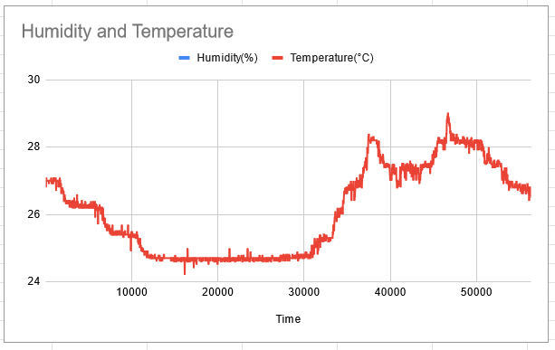
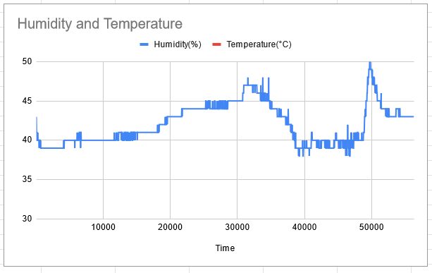
The resolution of the humidity sensor is less than the temperature sensor, which is why the temperature graph is more detailed.
How it works
Pico Code
The pico runs on a loop where it sleeps for the delay period, then requests a sensor reading from the DHT11, which stores temperature, humidity and a timestamp in an array of 7 byte records.
The pico has a number of general purpose input output (GPIO) pins that detect whether the voltage across it is high or low. So by connecting the DHT11 to one of the GPIO pins the pico and send and recieve data from the sensor. The specifics of how the data is sent can be read about here.
The DHT11 outputs 2 bytes for both temperature and humidity (but humidity only has 1 bytes of precision, it outputs two so it’s compatible with the DHT22), as well as a check byte. This data is stored as bytes, the conversion to floats happens with the command line tool. I also have the pico store the time as 3 bytes, so it can store up to 190 days of timestamps. An interrupt occurs when the pico recieves data to the uart1 port, which is stored as a char array. A command is finished with a CRLF, which tells the pico to check the given command and execute it, as well as clear the command char array.
The pico returns a 1 byte response code to the given command: 1 meaing a confirmation, 2 meaing an empty buffer, 3 meaning an unknown command. In the case of a get command, the pico send 8 bytes for each recorded sensor reading. 7 bytes are for the data, and 1 byte is for syncing. This make sure missed bytes only affect two records, instead of offseting every byte afterwards.
The pico then resets it’s time, clears it’s buffer and continues getting sensor readings. The buffer size is 30,000 (this is 210kB, pico has 256kB ram total), so at the default reading of every 30 seconds, it should be able to run for 10 days without needing to be emptied.
The reading interval can be checked and changed with a delay command, which uses the same codes as the first command, then recieves a 1 byte number representing the delay in seconds, and returns the byte for checking.
Command Line Code
This is my first time working with Rust for something relatively low level like uart, and I found it a pleasant experience. The language made handling buffers very flexible, and the error handling was easy to implement.
The command line code uses the specifics of how the pico software sends it’s data/recieves commands. When asked to by the user, it sends a get command to the pico and reads 8 bytes per record, checking that the sync byte is correct. The user can get the current reading delay, or change it to something else (limted to the range of 1-255 seconds)
I wrote the tool to being very careful to check the user command is correct before getting the data, but once the program gets it from the device, it will rarely run into a stopping condition, this is to ensure that the data is usually preserved when an error occurs, even if it turns out to be a bit mangled.
The tool uses the serial port crate which exposes a cross-platform serial port api for connecting to and using ports.
Setup
If you want to use the software to run a cheap temperature recorder, these are the steps to follow. The components ended up costing me around £12.
You’ll need:
-
Some sort of uart device with a baud rate set to 9600, such as the HC-05 bluetooth module
-
A 5V power supply (can use batteries), or you can power over usb.
-
Some wires for connecting the pins to the components, I used a breadboard and dupont wires.
-
A micro usb to flash the software onto the pico.
-
A windows or linux computer for running the command line tool to grab the data from the pico
Download the binaries from the release section of the github page. You’ll need pico-th-collector.uf2 and either the windows cli or the linux cli. First install the software by holding the BOOTSEL button and plugging the pico into a computer. The pico should open as an external flash drive, now drag the .uf2 file onto the pico. The pico is now flashed with the software.
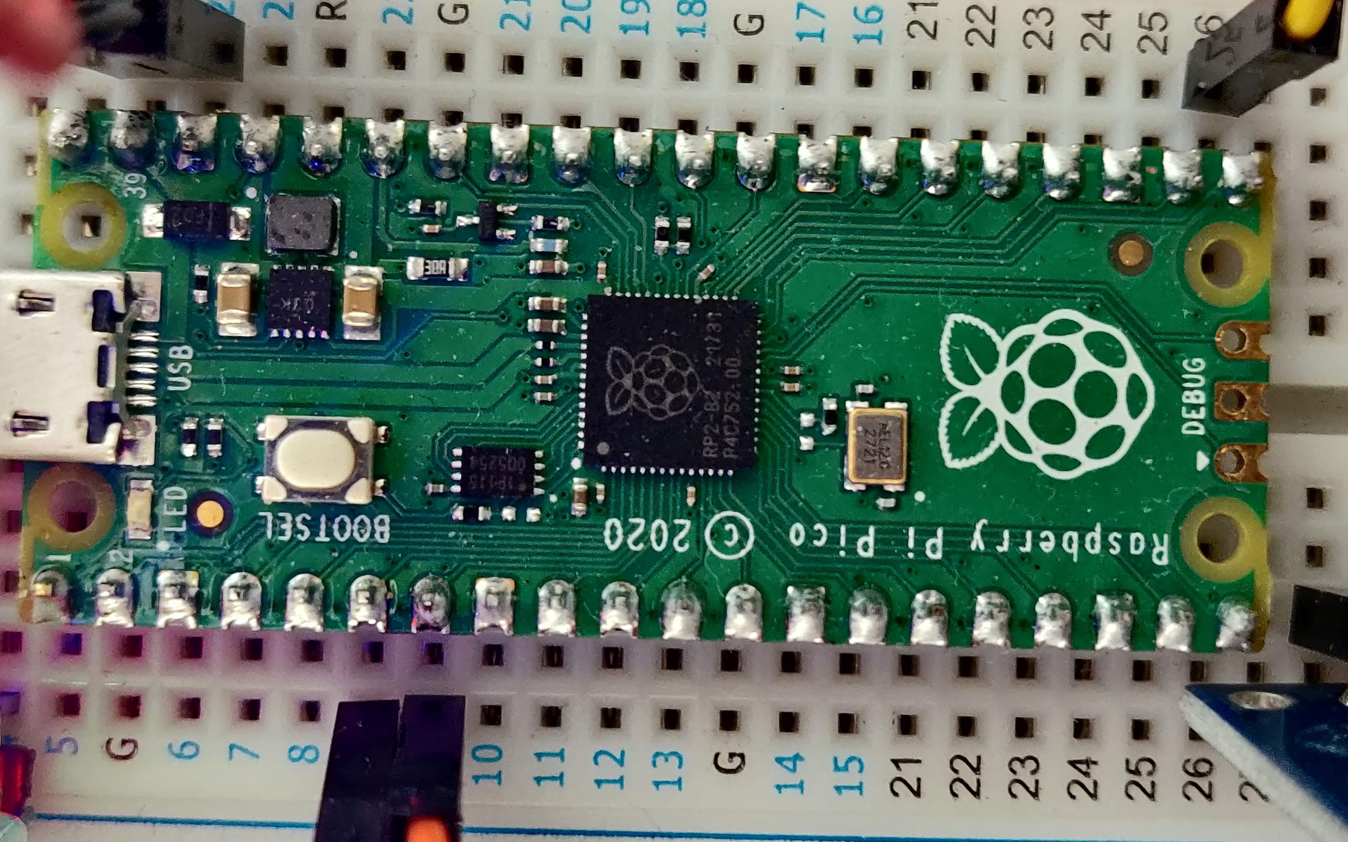
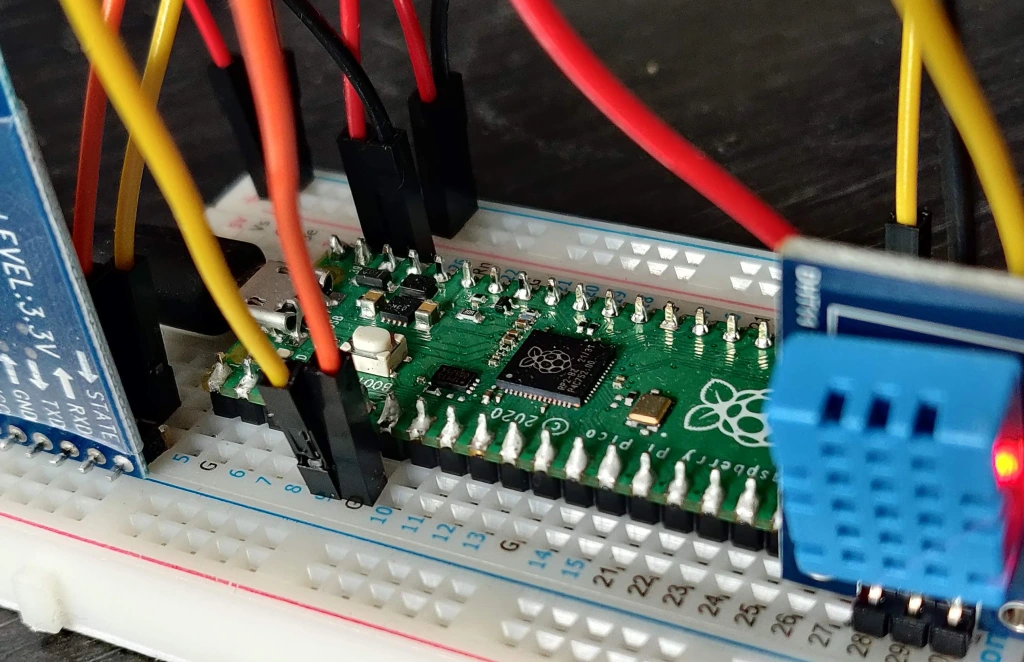
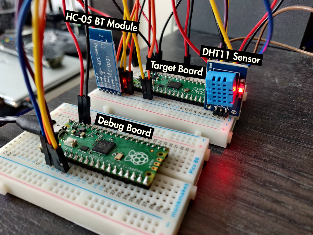
Next wire up the pico as shown below:
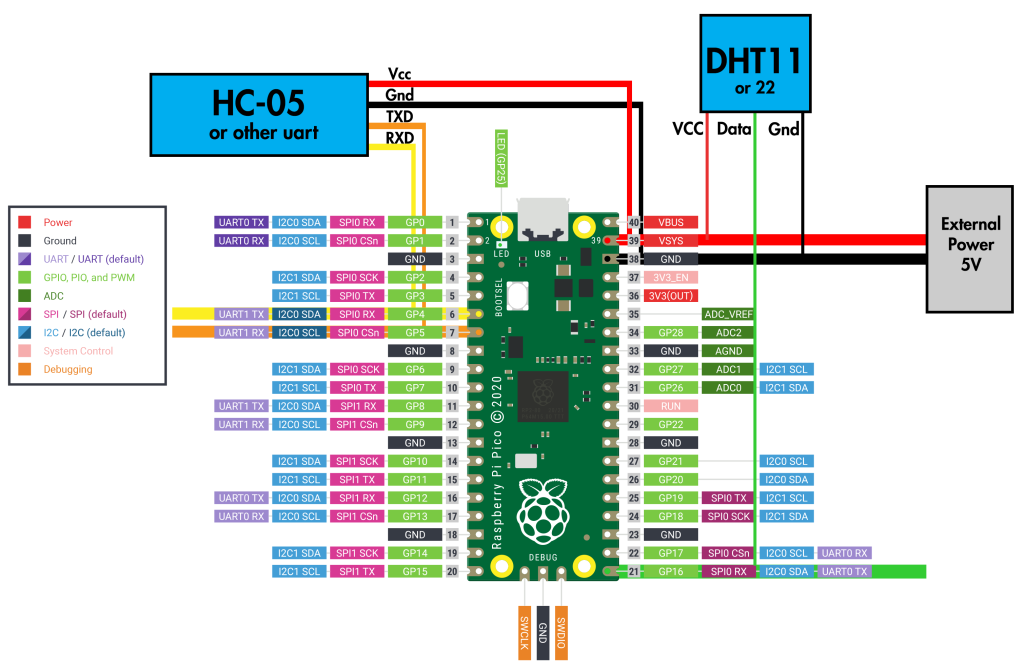
This is the information show in the image, with the pins named:
Pico -> DHT11
-
pin 21 GPI16 -> Data
-
VSYS -> VCC
-
GND -> GND
Pico -> HC-05
-
pin 6 UART1 TX -> RXD
-
pin 7 UART1 RX -> TXD
-
VSYS -> VCC
-
GND -> GND
Power Supply
-
VSYS -> positive terminal
-
GND -> negative terminal
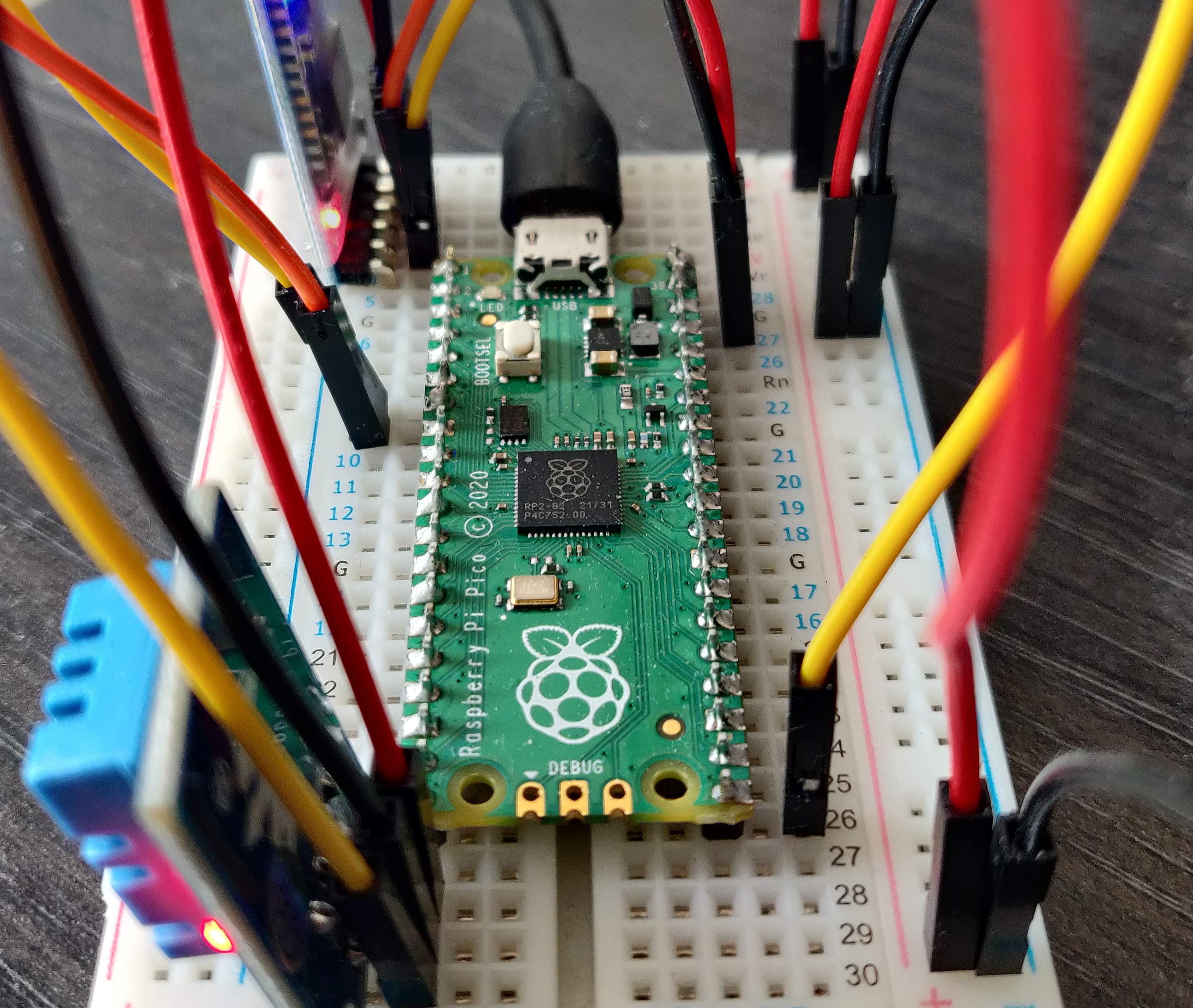
Note that the power supply doesn’t have to be connected to the VSYS and GND pins, plugging a usb into the micro-usb plug will also work.
Powering through USB:
Powering through battery:
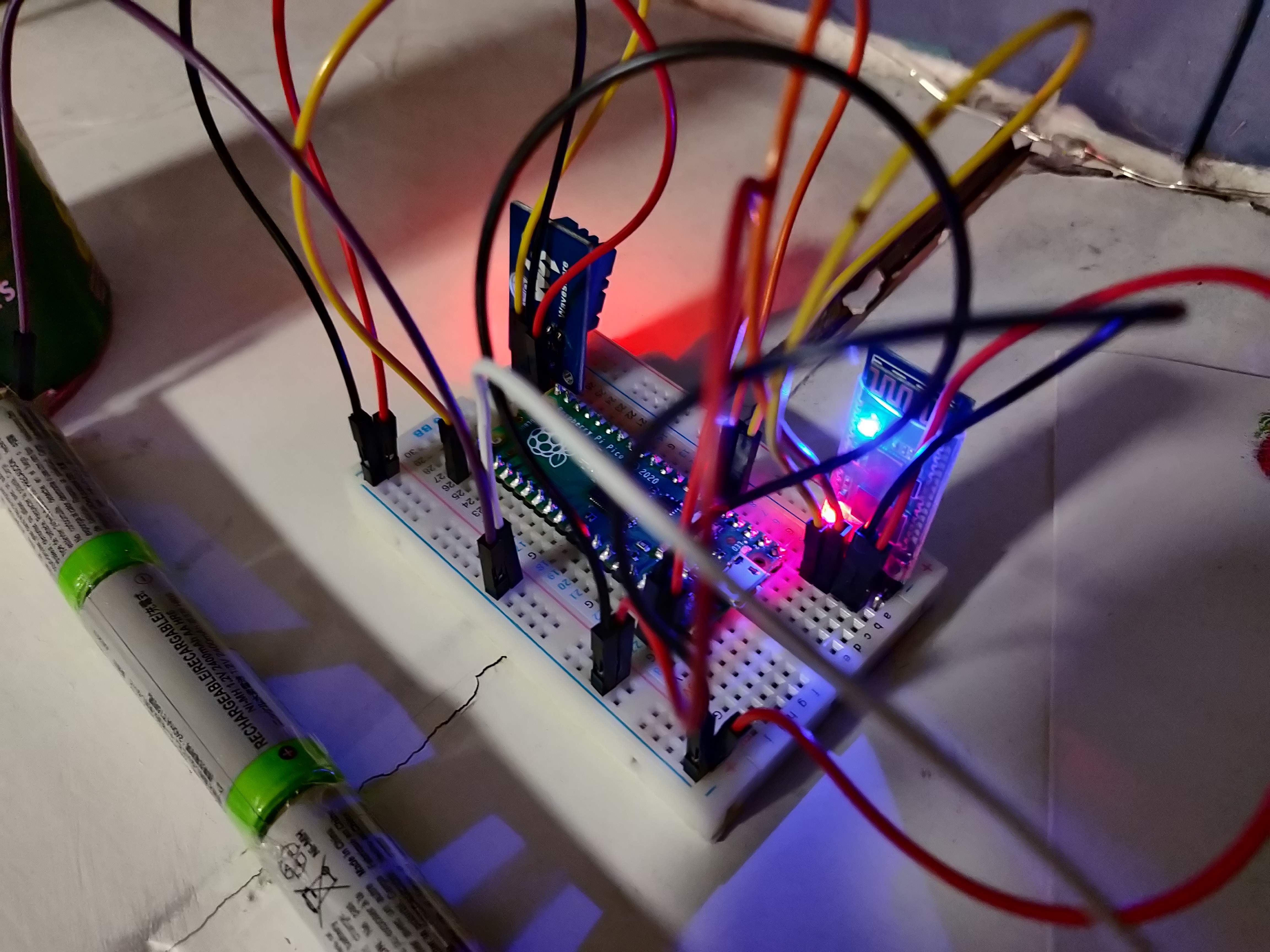
Now the pico can be left to collect data, the LED on the pico should flash every time it collects a reading.
Using the Command Line Tool
The pico can send you it’s collected readings over uart. You’ll need either a Window or Linux computer (and bluetooth if using uart bluetooth). If you have a mac, or the binaries don’t work on your architecture, you will need to build the command line tool yourself using Rust (See Building the Command Line Tool at the end of this article).
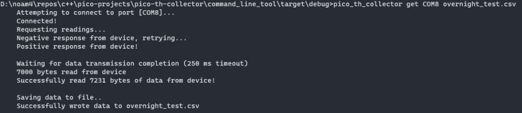
get command
The get command is used to get the data from the pico and save it to a file. It is used as
get [port] [file] [optional args]
[port] is the name of the port that the pico’s uart1 is connected to. If you are using bluetooth uart, you will first need to pair your device with the bluetooth module before you can use the port.
If you are on windows, the device manager will show your available ports under Ports (the format is COM[X]), you can either try them all with the command line tool, or connect and disconnect the pico to see which port appears and disappears.
On linux the dmesg | grep tty command will output a history of usb devices connecting, the port will be in the /dev/tty[device] format. If you are using bluetooth you can pair with the device using bluez, then link it’s MAC address to an rfcomm port, so the port format would be /dev/rfcomm[x].
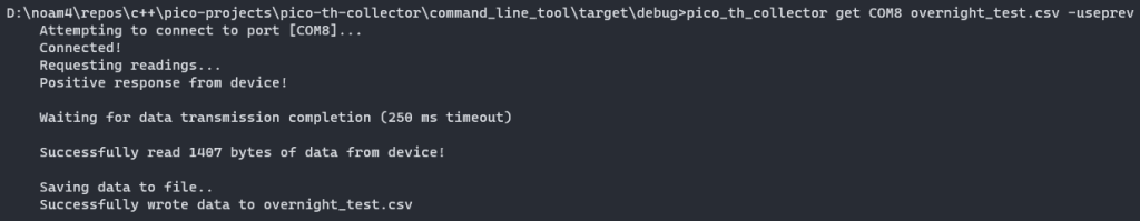
If the specified file already exists and is full of previous pico data, the user can specify the -useprev tag with the get command to use the last record in the file as an offset for the current data. This is used if you fetch data from the pico a second time after allowing it to continue to collect data.
The -useoffset [offset in seconds] tag will add the specified offset to the data (this can be used in conjunction with other args). This is useful if you want to append to preexisting data but the pico was off for a known time.
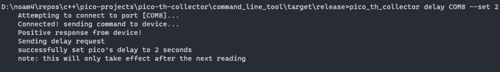
delay command
The delay command is used to get and set the reading delay of the pico. It is used as:
```
delay [port] [optional args]
``
Running the command without optinal args gets the current delay. The argument --set [delay] sets the pico’s delay to the given value in seconds.
Pico Development Setup
If you want to modify the software, if you would like to change the GPIO pins or the uart port or anything else, or build the binaries for yourself, these next sections will help.
Pico Debugging Setup
The pico is designed to be used with a raspberry pi computer, which acts as a debugger for the board. As an alternative for those without a pi pc, raspberry pi offer software called picoprobe which, when flashed onto a pico, allows that pico to act as the debugger.
The three debug pins at the bottom need to be hooked up to the debugger pico and ground. It can also share power with the slave pico. The debugger lets you flash new software on the pico, set breakpoints, and see a log of any errors.
For debugging, the debugger pico’s pins 4-GP2 (pin-label) and 5-GP3 are connected to the target’s SWCLK and SWDIO pins respectively. Wiring 39-VSYS and 38-GND to each other let the picos share power. You can also connect the debugger’s 6-UART1_TX and 7-UART2_RX to the target’s 2-UART0_RX and 1-UART0_TX respectively to pass the target pico’s uart0 through the debugger. Illustrated below (without the components connected):

For debugging software setup see Getting Started with Raspberry Pi Pico under Appendix A: Using Picoprobe. The dependancies section on the github repo also indicate which tools are needed for building the pico software.
Building the Command Line Tool
The command line tool uses Rust, which you will need to install. This comes with the package manager cargo, which will make building the binaries simpler by managing it’s dependancies for you.
Once you have Rust, download the source code for the command line tool and navigate to it. Run cargo build --release to build the binaries in release mode. The binary will now be in target\relase\ in the code directory.